Introduction
The purpose of this exercise was to experience a UAS, an Unmanned Aerial System. We were exposed to various UAVs (Unmanned Aerial Vehicles) and were lectured on their platform attributes along with their strengths and weaknesses in various situations. When choosing the proper UAV, a lot depends on the project at hand and it's constraints, be they flight time, stability, takeoff distance, ect.
This exercise contained three components. The first was a viewing of various vehicles and their attributes, a short lecture by Prof. Hupy about applying the right vehicle to the projects, and a flight demonstration on the Chippewa River floodplain. We flew the DJI Phantom and gathered aerial imagery of features on the floodplain. The second component of the exercise was taking the data collected from the DJI and creating a high pixel image interpretation using a point cloud with Pix4D software. This component focused on UAS related software so we also explored creating a flight plan with Mission Planner Software, and tested out our own UAS driving skills with Real Flight Simulator. The third component of the exercise was to apply our knowledge of UAS and select the most appropriate vehicle for a given scenario.
Methods
Part 1: Demonstration Flight
One of the most important aspects of UAS is having enough knowledge of UAV attributes in order to make the most efficient and cost-effective selection. Aerial systems can range from helicopters and drones, to fixed wings airplanes, and to kites, balloons, and satellites. For this exercise we focused on multirotor and fixed wing aircraft.
The first UAV we saw was a fixed wing aircraft composed mostly of styrofoam. (Figure 1.)The components included the "brains" of the craft; Pixahawk-3D robotics. This system was the flight control of the craft. The modem incorporated into the craft communicated with a computer on the ground or at a base station. It allows the craft to essentially fly itself, which differentiates it from RC or 'remote controlled' craft which are controlled by someone on the ground. Another component of the fixed wing was the antenna which served as a receiver, a battery which powered the craft, and a hook which is used with a bungee launcher to propel the craft to a high enough initial velocity to achieve flight. After the launch, the internal mechanisms take control over maintaining flight. Many UAVs can be outfitted with additional components in order to achieve the goals of the flight mission. This fixed wing aircraft contained a POM, or Personal Ozone Monitor. This device can be used to detect ozone levels a various altitudes and locations and attaches a GPS location with the data, which environmental scientists can map and analyze.
 |
| Figure 1. Internal mechanisms of styrofoam fixed wing aircraft. Note the antenna, modem, Personal Ozone Monitor and other flight components. |
An advantage of this UAV is its long flight time of 1.5 hours. A longer flight time means more time to collect data for analysis. Another advantage is that a fixed wing provides for a stable flight due to its internal mechanisms and broad wings. (Figure 2.)This prevents data skewing due to craft pitch, haw, or roll. A disadvantage of this system is that it's batteries do not provide a lot of energy output as related to their weight which means that a large portion of energy is required to accommodate for the weight of the battery. Another issue is that the batteries are highly volatile and have been known to combust spectacularly when overheated. This of course provides a dangerous component, not only to the system itself, but also for bystanders and flammable study areas.
 |
| Figure 2. Broad wing of the fixed wing aircraft. The wings were detached for storage and transportation purposes. |
The next UAV we observed was a Multirotor Quad Helicopter. (Figure 3.) The "quad" describes the four rotors. The rotors spin in opposite directions which is beneficial to efficient upward force. With the four wings an operator can control the rate of speed and how the craft steers.
 |
| Figure 3. Multirotor Quad Helicopter |
A benefit of this craft is that it can be launched straight up which is beneficial in places with not a lot of launch space such as the deck of a boat. Another benefit is that because each rotor can be controlled independently, it is more agile than the fixed wing aircraft. A disadvantage is that like the fixed wing, there is not a lot of payload for the energy input required. More torque is needed, and is shown in the Multirotor with six total rotors (Figure 4.). This craft can handle wind better and has more energy output than the quad helicopter. Both of these crafts handle easier than the fixed wing, and can make tighter turns. However, both of thee crafts have a shorter flight time of less than ~35 minutes.
 |
| Figure 4. Multirotor Helicopter with 6 rotors. |
After the UAV lecture we moved to the study area on the Chippewa River Floodplain. This area was chosen because it was relatively flat, had features we could easily map from an aerial view including rock features and the UWEC pedestrian bridge. It was also decently free of foot traffic and obstacles such as trees, buildings, and territorial birds of prey. Professor Hupy discussed the various safety methods and the startup procedure. (Figure 5) We then observed a flight and took aerial pictures using a stabilized camera. (Figure 6) I had the opportunity to fly the craft and found it not as easy as Professor Hupy made it seem. I am prone to crashing aircraft as shown in the subsequent flight simulator and was therefore hesitant to perform any drastic manuvers with the craft lest I cause a budget strain for the UWEC geography department.
 |
| Figure 5. Professor Hupy demonstrating proper safety and startup procedures. |
Figure 6. Drone footage.
Part 2: Software
Another huge component of UAS is being able to convert the data into a usable format. For this we explored Pix4D, a software that uses cloud point mapping (Figure 7.) to convert images to maneuverable geographic data.(Figure 8.)
 |
| Figure 7. Feature shown using cloud point mapping. |
 |
| Figure 8. Data imported into Pix4D for mapping |
The processing took a long time so I went ahead and used the Real Flight Simulator in the other room for 45 minutes while the program ran in the lab. The first set of data was disrupted because although the progress bar said 100% completed, I didn't wait until I saw the success message (Figure 9.) and exported the file too soon which corrupted it and caused it to be useless.
 |
| Figure 9. Success message detailing the quality of the resulting feature. |
I reran the process using only 12 images and found that the processing was much quicker. I then opened the resulting image in ArcMap and added background base mapping available from the previous lab. I found that the resulting map was very accurate and placed the image precisely where it occurred in the real world. (Figure 10.) (Figure 11.)
 |
| Figure 10. Ortho Map. Location of the resulting feature exactly where it occurs in the physical world. |
 |
| Figure 11. DSM Map. Note that the river level changes but the feature is accurately displayed. |
Another software we used was Flight Plan Mission Planner.(Figure 12.) This software allowed us to plan out theoretical missions and tweak factors to our imaginary constrictions such as flight time, altitude, and the amount of images we wanted to capture. I was surprised when tinkering with it to learn how many features were codependent on others. At some times these dependency's seemed almost counterintuitive until I reasoned through it. I explored and manipulated the effect of altitude, (Figure 13.) speed of the UAV (Figure 14.) and angle (15.)
 |
| Figure 12. Default values of Mission Planner software. |
 |
| Figure 13. Manipulation of altitude. |
I found that as altitude increased, the total amount of passes decreased. This is because more of the area will be included in the frame of the camera lens so fewer passes are needed. However, fewer images at a higher altitude will increase the level of distortion at the edges of each image. These distortions will need to be accounted for either in post processing or in additional flights.
 |
| Figure 14. Manipulation of the UAV speed. |
The speed of the craft only had an effect on the total flight time of the project. It likely depends on camera speed but I would have thought that there would be a decrease in photo resolution or quality. Practicality issues that are not easily accounted for also arise such as what speed is physically capable for a particular UAV and potential danger to spectators and wildlife.
 |
| Figure 15. Manipulation of angle. |
Angle was the final factor I manipulated. Because this project ran North to South, a change of angle only served to slow down the process as more time was spent flying over what wasn't included in the study area. This could be helpful in other project's whose orientation is not aligned with the cardinal directions.
In order to give us a better hands-on understanding of the differences between fixed wing and multirotor aircraft, we logged a half hour of flight time for each using Real Flight Simulator Software. This gave us the chance to 'play' with each platform and explore it's aspects without the danger of potentially costly damages and crashes.
The fixed wing system I simulated for 30 minutes was a Sea Plane model. (Figure 16.)
 |
| Figure 16. Sea Plane Scenario |
I found that, as I expected, there was a major learning curve. My initial flight was decimated within fifteen seconds as I was feeling out how the controls worked. The next three or four flights ended the same way. However, after I discovered which controls did what, it became fairly intuitive although my total flight times remained short. I found that it was much easier to control the craft at high speeds, but if I made a mistake, it was much harder to correct. I found that the craft was fairly stable compared to the other simulations which I attribute to the broad wings and landing mechanisms. I admit that I chose the simulation and how I tried to land based off of an scene in the cartoon sitcom, Bob's Burgers. (Figure 17)
Towards the end of the simulation, I found I was able to successfully fly the craft upside down which was amusing but likely not practical in real world situations lest I become a stunt pilot. Overall I found the exercise very instructive and far less expensive than if I was to learn by myself. (Figure 18.)
 |
| Figure 18. End of the fixed wing aircraft simulation. |
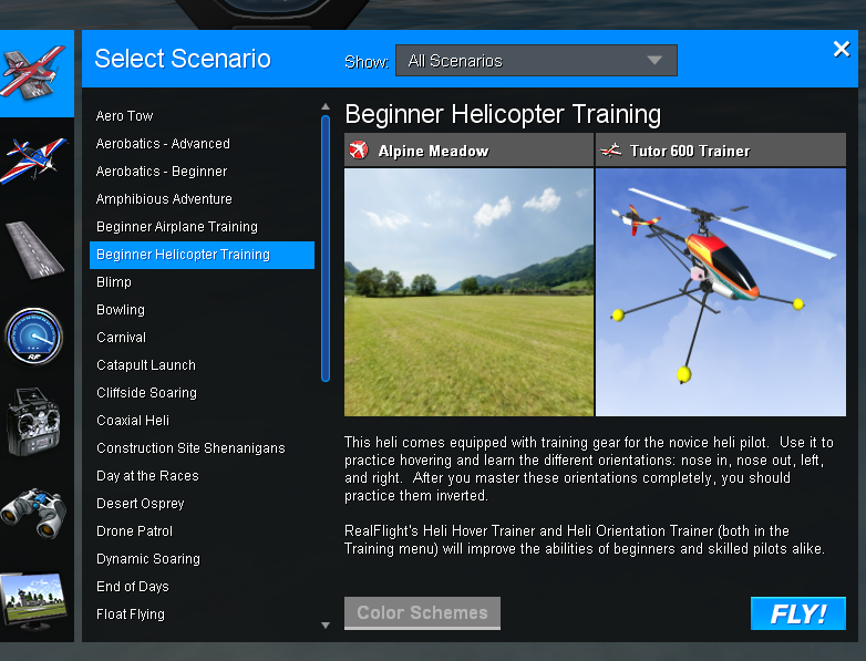
The second UAV I ran a simulation with was with a helicopter. (Figure 19.)
 |
| Figure 19. Beginning Helicopter simulation scenario. |
I found this a far more difficult UAV to fly, perhaps because I could not have a 'chase' view and had to observe it from the ground, as one would do if they were actually controlling it. This made me less motion sick, but I found it much more difficult to determine my intended direction as compared to my actual direction and orientation. Start up was an issue because I struggled with the order of operation for flight. The pre-flight figure was helpful in determining the function of some of the controls. (Figure 20)
 |
| Figure 20. Startup controls that provide for a safe launch. |
My flight times were far shorter because I resorted to simply 'hopping'; taking off and landing multiple times, slowly increasing my altitude until I felt mildly comfortable. I found the stability of the craft much harder to work with as very little steering caused the helicopter to veer off wildly. Steering was far less intuitive and there were very few soft landings. I found that durability was also a major issue as compared to the seaplane. I felt, rather resentfully towards the end of the simulation, that the helicopter would break if I simply looked at it wrong. (Figure 21.)
 |
| Figure 21. End of the Beginning Helicopter simulation. |
Overall, I found the helicopter far less intuitive and much less forgiving to a novice operator. I enjoyed the stability and ease of operation of the sea plane, although the helicopter was faster and more precise in it's movements. I understand how each has its strengths and weaknesses as applied to a project.
Part 3. Scenario
A pineapple plantation has about 8000 acres, and they want you to give them an idea of where they have vegetation that is not healthy, as well as help them out with when might be a good time to harvest.
I would suggest implementing a plan using a lightweight fixed wing UAV. 8000 acres of cropland is a large area so a helicopter or quad copter would not be as efficient. Multirotors specialize in precision operations because they are agile and easy to steer over small areas to obtain precise details. Because of the broad nature of cropland, the long takeoff distance of a fixed wing UAV is not a negative factor. A fixed wing UAV would be a good choice because it can fly for a longer period, on average 1.5 hours, it will have ample room to turn corners at the ends of the field, and the photos it will obtain will be taken in a more stable manner. I would suggest that the fixed wing UAV be outfitted with a camera that can collect an NDVI, or Normalized Difference Vegetation Index. This will help them see differences in crop health easier than with normal satellite photos and the images will have a higher resolution because the area is focused.
Conclusion:
This exercise was an important exposure to UAS and their platforms. Much of geography is trending towards the new possibilities that UAS offers and I believe that this technology will become increasingly relevant. It was exciting to control a UAV and participate in data collection. Data processing, which is often overlooked compared to the flashier 'drone' aspects, is also extremely important and I'm glad that I was able to process some data. It was also very useful to simulate both a fixed wing aircraft and helicopter in a way that causes no danger to anyone.


No comments:
Post a Comment